Case Study · Custom Engineering
Pressure Vessel Coating: 90-Foot Modular Dual-Chamber Inflatable Booth
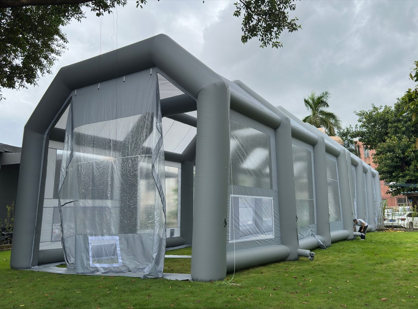
A returning customer came back with a far harder requirement: full-size pressure vessels that had to be coated inside a clean, contained environment — and moved in by rail. California, USA.
Client profile
| Industry | Pressure vessel manufacturing |
| Location | California, USA |
| Client type | Returning customer — previously bought a smaller Sewinfla booth |
| Application | Industrial spray coating of full-size pressure vessels |
The challenge — two constraints that ruled out any off-the-shelf booth
1. Extreme span
The booth had to reach 90 feet in length to enclose the vessel and the full coating workspace. A single inflatable chamber of that length sags and collapses at the midpoint under its own structural load.
2. Rail-cart access
The vessels could not be lifted or manually positioned. They had to roll into the booth on a rail-mounted cart — which meant a conventional built-in floor would obstruct the track.
The constraint. A standard long single-chamber booth fails structurally at the midpoint, and a standard built-in floor blocks the rail track the client already uses to move vessels. Both problems had to be solved in the same build, without asking the client to change their handling process.
Our custom solution
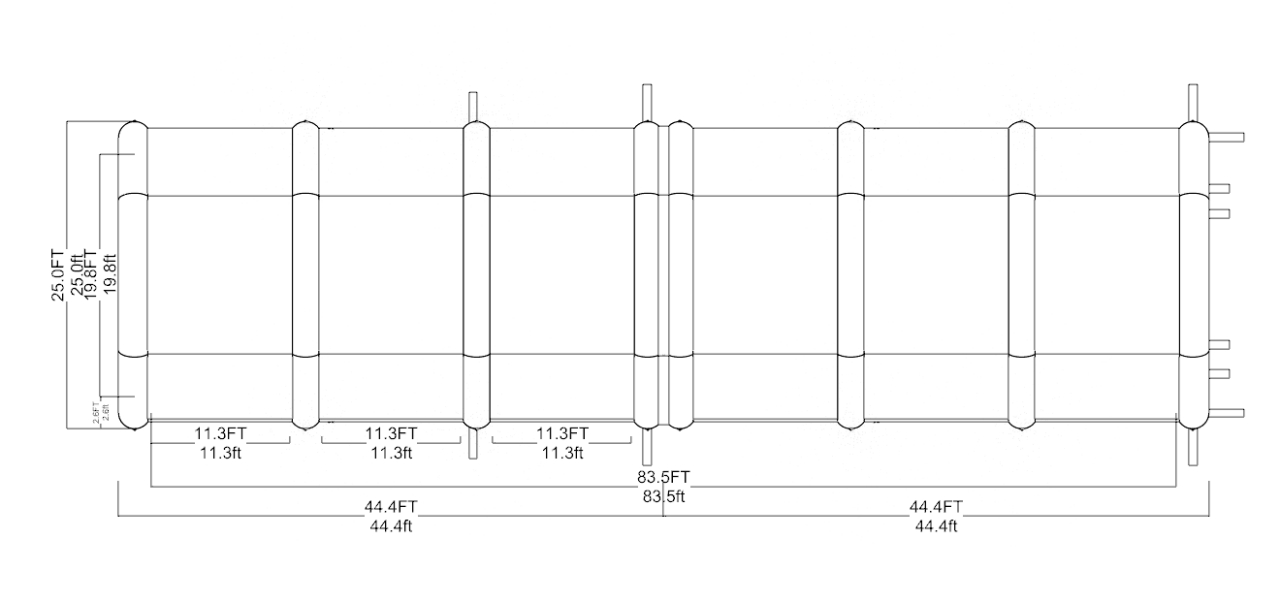
A purpose-built 90 × 25 × 20 ft (27.4 × 7.6 × 6.1 m) inflatable spray booth with two defining design decisions.
Design 1 — Modular dual-chamber construction (2 × 45 ft sections)
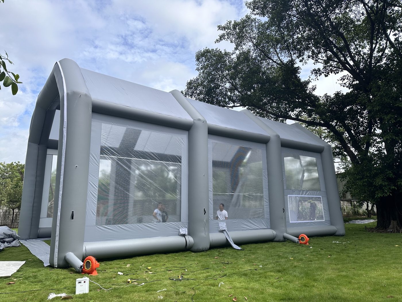
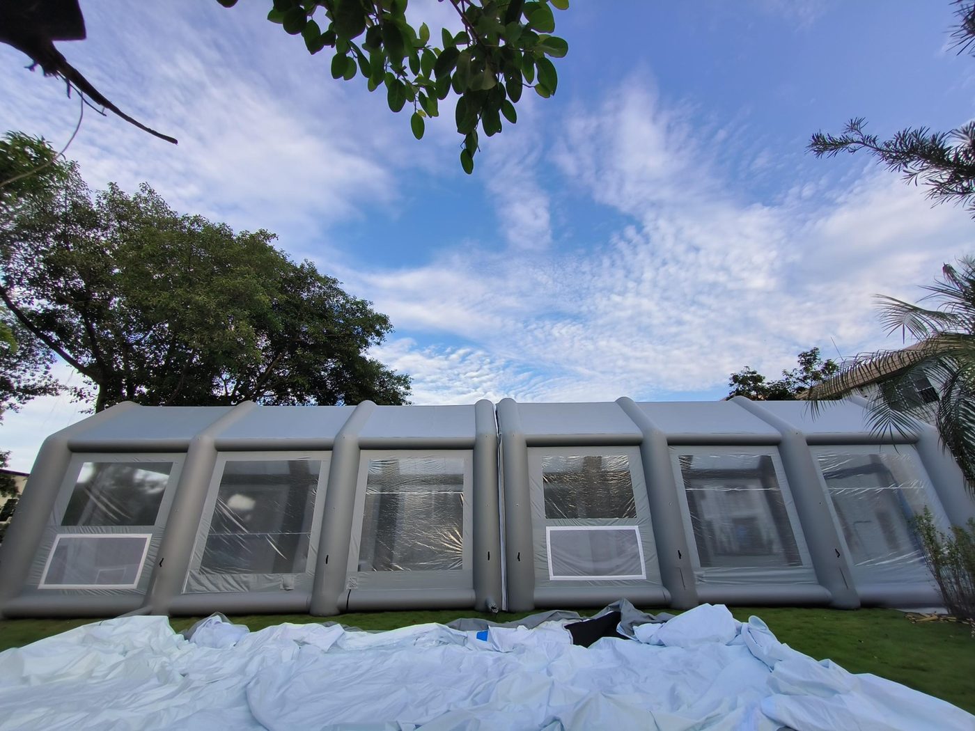
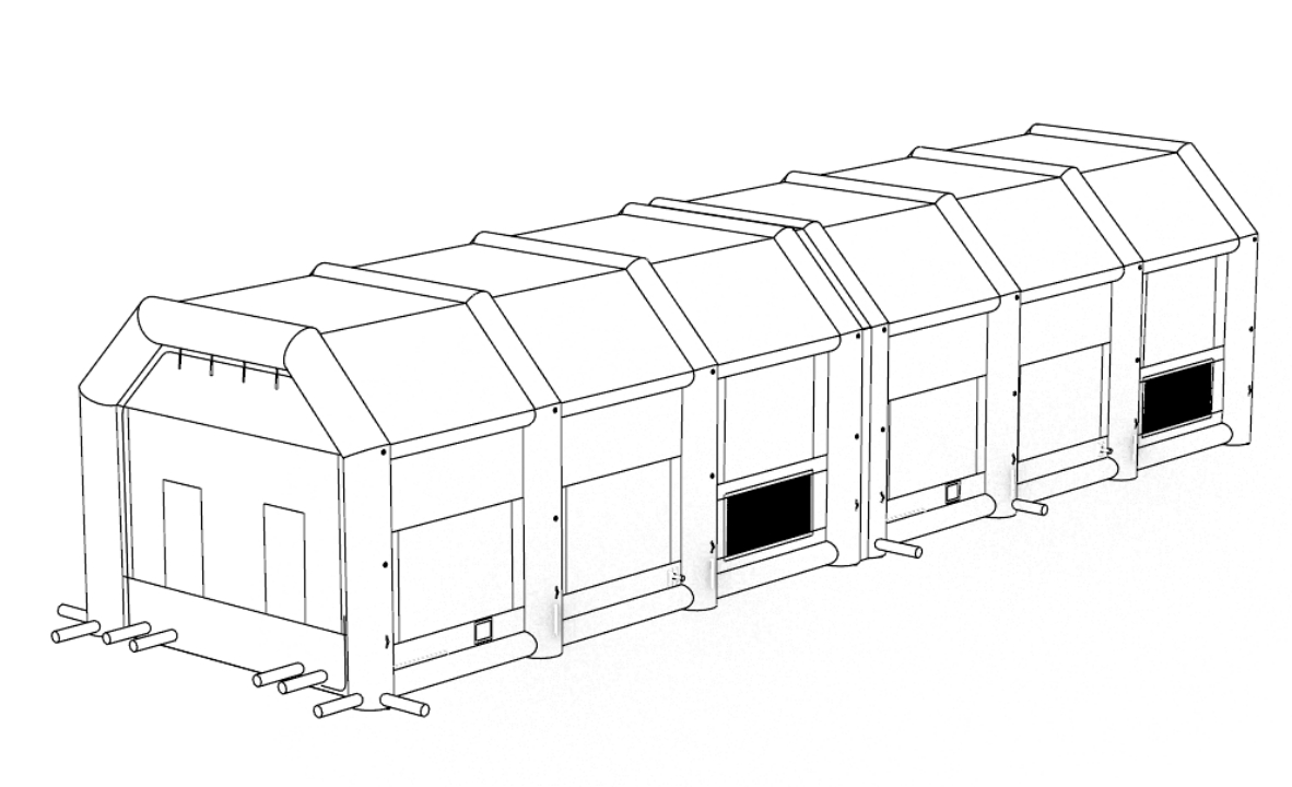
Rather than a single 90-foot chamber, the booth is built as two independent 45 × 25 × 20 ft sections joined together. Each section is a complete, self-supporting structure with its own air columns and load-bearing frame.
- No single unsupported span across the full 90 feet.
- Each section carries its own structural load, keeping the ceiling taut and fully supported end to end.
- The joined seam becomes a natural structural node — reinforcing the exact midpoint where a single long chamber would be weakest.
Design 2 — Removable Velcro bottom
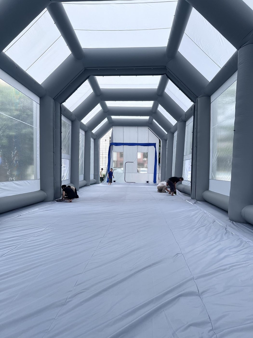
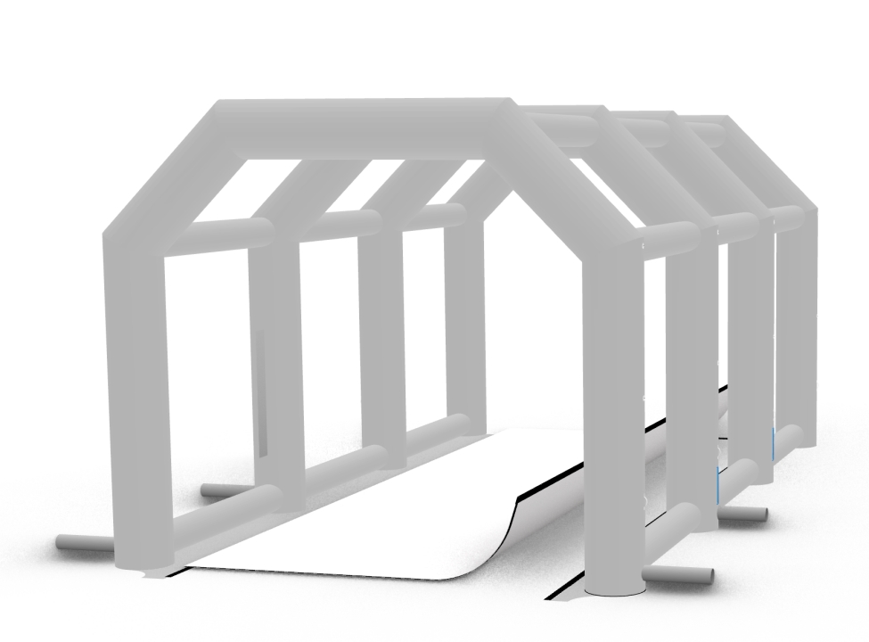
The standard built-in floor is replaced with a removable Velcro-attached bottom, engineered specifically for the client’s rail system.
- The rail track runs uninterrupted through the booth, so vessels roll in and out on the cart with no lifting and no obstruction.
- The bottom seals closed for overspray and dust containment during coating, and opens for track access and cleaning.
- Velcro attachment keeps the booth adaptable — sealed when coating, open for rail movement — without sacrificing containment.
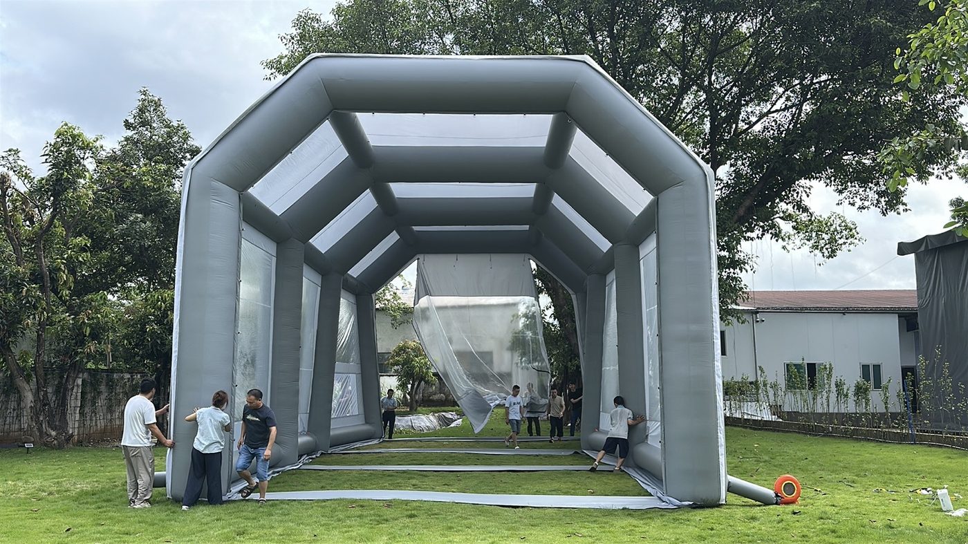
Factory testing photographs
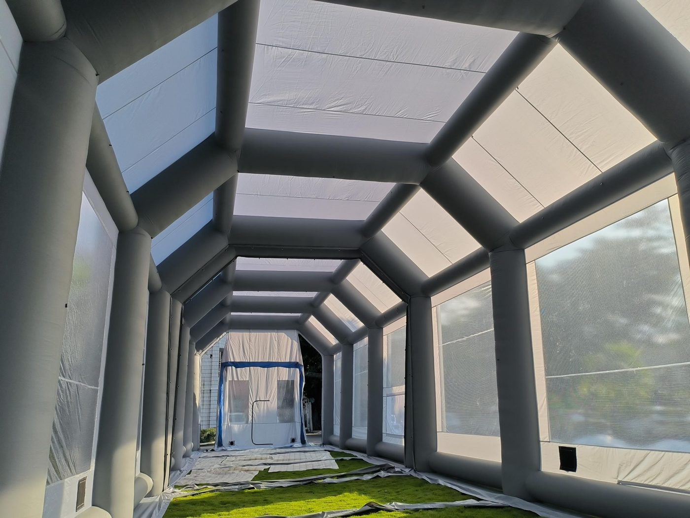
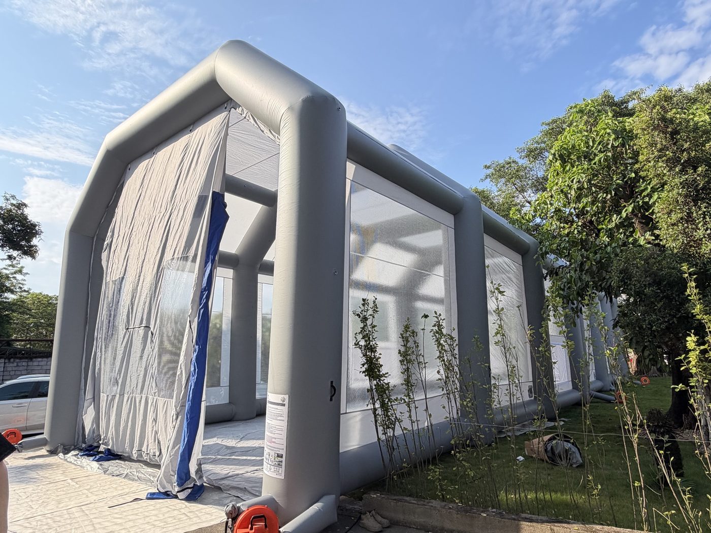
Taken during factory testing, when the completed booth was erected and inspected before crating. They document the structure as built — not the client’s operating site.
Design models
Production engineering models of this build — not photographs of the installed booth.
Specifications
| Overall dimensions | 90 × 25 × 20 ft (27.4 × 7.6 × 6.1 m) |
| Construction | Two 45 × 25 × 20 ft modular chambers, joined |
| Floor | Removable Velcro-attached bottom |
| Vessel access | Rail-mounted cart (track-compatible) |
| Application | Large pressure vessel spray coating |
Approximate. Handmade inflatable product, vary with air pressure/standing conditions. Product received prevails.
Why this approach
- Structural integrity at scale. Long single-chamber inflatables fail at the midpoint because one air column cannot hold tension across 90 feet. Splitting the span into two independent chambers turns a structural weakness into a support point.
- Workflow-first engineering. Instead of asking the client to change their process, we adapted the booth to their existing rail-cart material-handling system.
- Modular investment protection. The two-section design can be reconfigured, relocated, or individually replaced — protecting the client’s long-term investment.
Results
The figures below are the client’s own operating estimates, reported to us. They describe this client’s workflow and are not a performance guarantee for other applications.
- Cycle time. On-site coating removes transport and lifting of large vessels, cutting total cycle time by approximately 35% (client estimate).
- Cost. Roughly one-quarter the cost of a permanent steel-and-concrete booth — about 75% lower upfront, with no permits or long-term maintenance (client estimate).
- Containment. A fully sealed enclosure with the removable floor keeps overspray and dust contained for clean coating.
- Flexibility. The modular two-section structure dismantles, stores and relocates, freeing floor space when idle.
What made this build different. The problem was not “make a bigger booth” — it was two structural decisions taken together: split the span so no single chamber carries 90 feet, and remove the floor so the client’s existing rail system keeps working. Both served the same goal: adapt the booth to the workflow, not the workflow to the booth.
What this case does not claim
Stated plainly. The client is not named; they are described by industry only. The cycle-time and cost figures are the client’s own operating estimates, not audited measurements, and are specific to this workflow. This is a custom-engineering build rather than a catalogue size — if your vessel geometry and access method differ, the design will differ with them.
Need a booth engineered around your workflow?
Send us your dimensions, your access method and your coating requirements — we will design a custom solution built for your exact process.