Why Ventilation Matters
Paint overspray isn't just a nuisance — it's a three-pronged problem that ventilation directly solves. First, overspray accumulation in a poorly ventilated booth creates a visible fog within 30–60 seconds of starting a spray pass on a full panel. That fog is atomized paint droplets suspended in air, typically 5–50 microns in diameter, that haven't been carried to the exhaust. They settle on the wet surface as a gritty texture — what painters call "dry spray" or "overspray dust." No amount of polishing removes it cleanly; you're sanding it out or re-spraying.
Second, the health hazard is real and immediate. Two-component (2K) automotive paints contain isocyanate hardeners that are respiratory sensitizers. Solvent-based single-stage paints off-gas toluene, xylene, and MEK at concentrations that exceed OSHA permissible exposure limits (PELs) within minutes in an unventilated enclosure. A properly designed ventilation system achieves 4–6 complete air changes per minute in the booth volume, keeping airborne contaminant concentrations below actionable thresholds. This isn't optional — it's the difference between a safe workspace and one that requires a supplied-air respirator.
Third, finish quality correlates directly with ventilation efficiency. When the exhaust fan pulls laminar (smooth, non-turbulent) airflow across the work surface, overspray is swept away before it can drift back onto the panel. Painters who upgrade from passive venting to a powered exhaust fan routinely report a 70–80% reduction in dirt nibs per square foot. The physics is straightforward: if overspray stays airborne for less than one second before reaching the exhaust, it has no opportunity to find a wet panel.
Exhaust Fan vs. Inflation Blower
One of the most common mistakes new inflatable booth owners make is conflating the inflation blower with an exhaust fan — or worse, assuming the inflation blower alone is sufficient for ventilation. These are two completely separate components with distinct engineering roles, and understanding the difference is foundational to proper ventilation design.
The inflation blower maintains positive pressure inside the booth — typically 0.3 to 0.5 inches of water column (inWC). Its job is structural: keeping the fabric walls rigid and preventing unfiltered outside air from infiltrating through seams and zippers. A typical Sewinfla booth inflation blower delivers 900–1,500 CFM depending on model size. This air enters through the intake filter assembly and pressurizes the booth, but it does not create directional airflow past the work surface — it simply fills the chamber.
The exhaust fan creates the directional airflow that carries overspray out. It's positioned at the exhaust port(s) and pulls air through the booth, past the workpiece, and out through the activated carbon filter. Exhaust fan CFM requirements are separate from — and in addition to — inflation blower CFM. A common configuration for a mid-size booth (20' x 12' x 9') is an inflation blower at 1,200 CFM paired with an exhaust fan at 2,500–3,500 CFM. The exhaust fan must move more air than the blower delivers because it's pulling against the filter media's flow resistance.
Running the inflation blower without an exhaust fan creates a pressurized but stagnant booth — overspray hangs in the air and visibility degrades rapidly. Running an exhaust fan without the inflation blower depressurizes the booth, causing walls to collapse inward and unfiltered air to rush in through every gap. Both components must operate simultaneously during spraying for the system to function correctly.
If you hear the inflation blower pitch change when you switch on the exhaust fan, your exhaust is overpowering your intake — the booth is losing positive pressure. Balance them by reducing exhaust fan speed (if variable-speed) or slightly restricting the exhaust opening until the blower pitch stabilizes. The booth walls should remain fully taut at all times.
CFM Requirements by Booth Size
Exhaust fan sizing isn't guesswork — it's a function of booth volume and the target air exchange rate. But the rate you size to depends on which kind of booth you are running, and the two regimes are not interchangeable. Getting this wrong is the most common airflow mistake we see.
Fixed downdraft or cross-draft booths. A permanent booth with a floor plenum or pit pulls air down through the entire working area, so it moves an aggressive volume: for automotive refinishing with solvent-based products the industry standard is 4–6 complete air changes per minute, and 3–4 per minute is typically sufficient for waterborne basecoats. Expressed in the units used for inflatable booths, that is 240–360 air changes per hour — which is why fixed installations use 10,000 CFM and larger fan packages. The reference table below is that regime, and the sizing formula is:
The efficiency factor accounts for flow losses through filter media, ducting, and bends — use 0.75 for a typical setup with 6–8 feet of flexible ducting and one activated carbon filter, or 0.85 for a short, straight exhaust path.
Reference: fixed downdraft / cross-draft booths (4–6 air changes per minute)
| Booth Size (L × W × H) | Volume (ft³) | Min Exhaust CFM | Recommended CFM | Typical Use |
|---|---|---|---|---|
| 13' × 8' × 7.5' | 780 | 1,560 | 1,800–2,200 | Motorcycle, bicycle, small parts |
| 16' × 10' × 8' | 1,280 | 2,560 | 3,000–3,500 | Compact car, door panels, hoods |
| 20' × 12' × 9' | 2,160 | 4,320 | 5,000–6,000 | Full sedan, SUV panels, full respray |
| 26' × 15' × 10' | 3,900 | 7,800 | 9,000–10,500 | Truck, large SUV, van, light aircraft |
| 33' × 18' × 11' | 6,534 | 13,068 | 14,000–16,000 | Commercial truck cab, boat hull, RV |
Inflatable positive-pressure booths. A Sewinfla-class booth is a fabric shell held rigid by a blower, with a cross-flow exhaust port rather than a floor plenum. Its internal air volume is exchanged far more slowly, and it is sized in air changes per hour using the same formula used throughout our engineering guides:
Use 60 ACH as the finishing baseline and step up to 90–120 ACH for solvent-heavy base and clear work. Because the total figure splits between an inflation side (blowers that hold the shell rigid and deliver filtered make-up air) and an exhaust side (the fan that removes the air volume), both must run during spraying — see the section above.
Sizing: inflatable positive-pressure booths (60–120 ACH)
| Booth Size (external) | Volume (ft³) | CFM @ 60 ACH | CFM @ 90 ACH | Rated capacity @ 1.3× |
|---|---|---|---|---|
| 13' × 8' × 8' | 832 | 832 | 1,248 | 1,080–1,620 |
| 20' × 13' × 9' | 2,340 | 2,340 | 3,510 | 3,050–4,560 |
| 26' × 15' × 10' | 3,900 | 3,900 | 5,850 | 5,070–7,605 |
| 28' × 15' × 11' | 4,620 | 4,620 | 6,930 | 6,006–9,006 |
Full derivation, worked examples, altitude and temperature corrections, and the blower selection table are in our Inflatable Paint Booth CFM Calculator guide.
In the fixed-booth reference table, the "Min Exhaust CFM" column reflects the bare minimum for 2 air changes per minute at 100% efficiency — not a safe operating target. The "Recommended CFM" column accounts for real-world filter resistance, ducting losses, and the 4–6 air changes per minute needed for proper overspray clearance. Undersizing your exhaust fan saves money upfront but costs you in rework, filter saturation, and health risk. Size up, not down.
Intake/Exhaust Placement
Where you position the intake and exhaust determines whether air flows through the booth or merely around it. The goal is cross-ventilation: fresh air enters from one end, travels linearly across the workpiece, and exits at the opposite end, carrying overspray with it. Any other configuration creates eddies, dead zones, or short-circuiting where air takes the path of least resistance without sweeping the spray area.
Upwind/Downwind Geometry
The inflation blower intake and the exhaust fan outlet must be on opposite sides of the booth, separated by at least 20 feet — and always oriented with the prevailing wind direction. Position the intake upwind (so the blower draws clean ambient air) and the exhaust downwind (so expelled solvent-laden air is carried away, not back toward the intake). If wind direction shifts during a spray session, you'll recirculate contaminated exhaust through the intake, saturating filters prematurely and introducing solvent vapors back into the booth. For permanent or semi-permanent installations, consider the site's seasonal prevailing wind patterns before anchoring the booth location.
Exhaust Duct Length and Routing
Exhaust ducting should be as short and straight as possible. Every 90° bend in flexible ducting adds the equivalent of 10–15 feet of straight duct in terms of flow resistance (static pressure drop). A 6-foot straight exhaust run with 0 bends is more efficient than a 6-foot run with two 90° bends — the latter effectively behaves like a 26–36 foot duct. If bends are unavoidable, use smooth-radius elbows (not crimped flex duct folded over) and keep the total effective duct length under 25 feet. Beyond 25 feet of effective length, you'll need to upsize the exhaust fan by 15–25% to compensate for static pressure losses.
Use a smoke pencil or incense stick to visualize airflow inside the booth before spraying. Hold it at various positions — near the floor, at workpiece height, at head height — and watch the smoke path. It should travel smoothly and directly toward the exhaust port, not swirling or drifting upward. If smoke lingers or circles, you have a dead zone that needs attention.
Air-Quality Compliance & Filter Selection
Paint spray operations in the United States fall under NESHAP's National Emission Standards for Hazardous Air Pollutants (NESHAP) for Paint Stripping and Miscellaneous Surface Coating Operations, codified at 40 CFR Part 63 Subpart HHHHHH (commonly called "6H"). While many small-scale and mobile operations are exempt from the full permitting requirements, the underlying engineering standards — particularly around filtration efficiency and capture — represent best practice regardless of your regulatory classification.
Filtration Standards & Air-Quality Compliance
Sewinfla booths are engineered around the same filtration principles that NESHAP and local air quality management districts (AQMDs) apply to fixed spray enclosures: staged particulate capture followed by activated-carbon VOC adsorption. The filter stack is specified by measured performance (MERV-rated particulate stages plus a known carbon weight per 100 CFM of exhaust flow) rather than by a registration number, so the specification can be verified independently against your local permit requirements.
Permitting is the operator's responsibility. Requirements vary by state, county, and coating chemistry, and many small-scale or mobile operations are exempt. The booth's filtration performance is designed to support the permit application process — it does not itself confer a permit, an exemption, or a regulatory certification. Confirm your obligations with your local AQMD before starting commercial spray finishing.
Sources checked 2026-09-21: OSHA 29 CFR 1910.107(b)(5)(i) — average air velocity over the open face or cross-section not less than 100 linear feet per minute (60 for electrostatic), with a gauge, alarm or pressure-activated device confirming it is maintained; Cornell LII 40 CFR Part 63 Subpart HHHHHH, § 63.11173(e)(2) — whole-vehicle spray booths fully enclosed and ventilated at negative pressure, and spray booth filters demonstrated to capture at least 98% of paint overspray under ANSI/ASHRAE Standard 52.2-2017 (ASHRAE standards library); NFPA 33 standard development page; NIOSH isocyanate guidance for spray operations.
MERV Ratings for Spray Booth Filters
MERV (Minimum Efficiency Reporting Value) is the ASHRAE 52.2 standard for filter efficiency across particle size ranges. For inflatable paint booth applications, three MERV ranges are relevant:
- MERV 8–10 (Pre-filters): Capture particles 3.0–10.0 microns at 70–85% efficiency. This is the fiberglass intake pre-filter range — designed to stop overspray droplets before they reach the blower or main filter. Replace when visibly loaded or after every 3–5 spray jobs.
- MERV 13–15 (Exhaust particulate): Capture particles 0.3–1.0 microns at 50–90% efficiency. Used as the particulate stage of exhaust filtration to catch fine overspray mist that escapes the booth interior. These filters are typically pleated synthetic media, not fiberglass.
- Activated Carbon (VOC adsorption): Carbon filters don't have MERV ratings — they're rated by carbon weight, bed depth, and contact time. A minimum of 2.5 lbs of activated carbon per 100 CFM of exhaust flow is the industry benchmark for automotive solvent capture. Thinner carbon beds (< 1 inch depth) saturate rapidly and provide minimal VOC reduction.
Filter Maintenance Schedule
Filters are consumables, not permanent fixtures. A clogged filter doesn't just reduce airflow — it increases the pressure differential across the filter media, which forces the exhaust fan to work harder, drawing more amperage and generating more heat. The filter replacement cadence depends on spray volume:
- Fiberglass pre-filter: Replace every 3–5 full spray jobs, or when a flashlight held behind the filter shows less than 50% light transmission compared to a new filter.
- MERV 13 exhaust particulate filter: Replace every 10–15 spray jobs, or when the exhaust fan amperage draw increases by more than 15% above baseline (indicating the fan is working harder against restriction).
- Activated carbon filter: Replace every 8–12 full spray sessions using solvent-based products. The telltale sign of carbon saturation is detectable solvent odor at the exhaust outlet — at that point, the carbon bed is at >90% capacity and must be replaced immediately.
Airflow Optimization Tips
Adequate CFM is necessary but not sufficient — you also need the air to flow where it's needed. The difference between a booth that has enough fan power and one that actually clears overspray is airflow management: baffles, duct design, and dead-zone elimination.
Baffles and Air Distribution
The inflation blower typically enters the booth at a single point, creating a high-velocity jet that can stir up settled dust and create turbulence around the workpiece. A simple diffuser baffle — a fabric panel or rigid board positioned 8–12 inches in front of the inflation duct opening — breaks this jet into a distributed, lower-velocity flow that fills the booth more evenly. This is especially important in longer booths (20+ feet) where the far end would otherwise receive minimal fresh air exchange.
Avoiding Dead Zones
Dead zones are areas where airflow velocity drops below ~50 FPM (feet per minute) — too slow to carry overspray. They form in corners, behind large workpieces, and in the lee of booth frame members. To identify dead zones: set the booth up with blower and exhaust running, walk the interior with a smoke source or velometer, and map areas of stagnant air. Common fixes: reposition the exhaust port to the geometric center of the end wall (not a corner), add a small auxiliary circulation fan inside the booth to stir dead-air pockets, or orient the workpiece so its long axis is parallel to airflow (not perpendicular, which creates a large wake zone behind the object).
Ducting Best Practices
Flexible ducting is convenient but aerodynamically inefficient. The corrugated interior surface creates turbulent boundary layers that increase static pressure drop compared to smooth-wall rigid duct of the same diameter. When possible, use rigid galvanized duct for the primary exhaust run, with flex duct used only for the final connection to the booth exhaust port. Maintain consistent duct diameter throughout the run — necking down from 12" to 8" at a connector creates a Venturi restriction that chokes flow far more than the diameter reduction alone would suggest. If diameter transitions are unavoidable, use gradual tapered reducers (minimum 15° included angle), not abrupt step-downs.
Temperature and Humidity Considerations
Exhaust fan CFM ratings are measured at standard conditions (70°F, sea level). At higher temperatures, air density decreases and the fan moves less mass flow for the same volumetric CFM. At 5,000 feet elevation, air density is roughly 83% of sea level — your 5,000 CFM fan effectively delivers 4,150 CFM in terms of air mass movement. Factor in a 10–15% CFM margin if you operate at elevation or in consistently hot ambient temperatures (90°F+). Similarly, high humidity increases air density slightly but introduces condensation risk in ducting — insulate exhaust ducts that pass through air-conditioned spaces to prevent moisture accumulation inside the duct.
Key Takeaways
- Inflation blower and exhaust fan serve separate roles — both must run during spraying; never substitute one for the other
- Size to the right regime: fixed downdraft booths at 4–6 air changes per minute with a 0.75 efficiency factor for filter/duct losses; inflatable positive-pressure booths at 60 ACH baseline rising to 90–120 ACH for solvent-heavy work, then × 1.3–1.5 for filter loading
- Position intake upwind and exhaust downwind with minimum 20-foot separation to prevent solvent recirculation
- Use MERV 8–10 fiberglass pre-filters on intake, MERV 13–15 on exhaust particulate, and 2.5+ lbs activated carbon per 100 CFM for VOC capture
- Keep exhaust duct runs under 25 effective feet; every 90° bend adds 10–15 feet of equivalent flow resistance
- Identify dead zones with smoke visualization and eliminate them with baffles, port repositioning, or auxiliary circulation fans
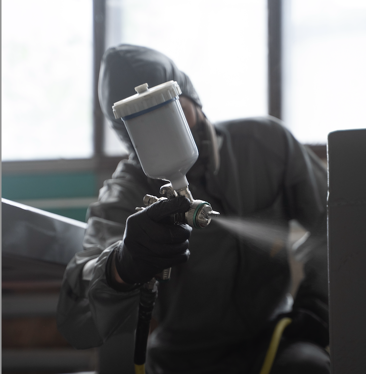
Complete Ventilation Systems — In Stock
Every Sewinfla booth is compatible with our matched exhaust fan kits — sized for your exact booth model. Dual-stage activated-carbon filtration included. Don't guess on CFM; buy a system designed to work together.
Browse Exhaust FansRelated Guides
- Inflatable Paint Booth CFM Calculator — airflow maths, derate factors and blower selection.
- How an Inflatable Paint Booth Works — the airflow circuit and activated-carbon filtration explained.
- Overspray Fog: Why It Happens & How to Fix It — diagnosing fog, and the airflow and technique fixes for it.
- How to Paint a Car in an Inflatable Paint Booth — the full walk-around respray workflow, from sizing to spray order.
- 210D vs 420D vs PVC: Material Comparison — what each fabric property is and how it is measured.